Fire Sprinkler Hydraulics: Featured Summary
Understanding fire sprinkler hydraulics is essential for designing NFPA 13-compliant systems. This article explains how flow rate, pressure, friction loss, pipe diameter, pipe roughness (C-Factor), and network configuration influence hydraulic performance. Using a simple real-world analogy, complex hydraulic concepts become easier to understand while maintaining engineering accuracy.
Introduction to Fire Sprinkler Hydraulics
Hydraulic calculations are one of the most important aspects of fire sprinkler system design. Whether designing systems in accordance with NFPA 13, evaluating hydraulic demand, or sizing sprinkler piping networks, designers must understand how water behaves as it travels through a system.
This paper explains fundamental concepts of fluid mechanics—such as flow, pressure, pressure loss, the C Factor, and internal pipe diameter—using simple, relatable examples. A clear understanding of these concepts empowers designers to perform hydraulic calculations more accurately and optimize systems more effectively.
Understanding Hydraulic Behavior Through a Simple Analogy
Setting the Scene
Imagine the blue circles in Figure A are people gathered in a saloon. Their task is to pass through a corridor to reach the yard, where they must lift and move 20-kilogram weights.
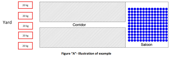
As people make their way through the corridor, they lose energy from walking, bumping into one another, and brushing against the walls. This energy loss could leave them too tired to lift and move the weights once they arrive in the yard.
This analogy highlights the importance of reducing energy loss so that people (or, in hydraulic terms, water) reach their destination with enough energy (pressure) to complete their task.
Key Insight
In fire sprinkler hydraulics, pressure is the "energy" available to move water through the piping network and discharge it effectively through sprinklers. Excessive friction loss reduces the available pressure at the point of discharge.
Case Studies Demonstrating Pressure Loss and Hydraulic Performance
Case 1: Reducing Distance
How Shorter Pipe Lengths Reduce Friction Loss
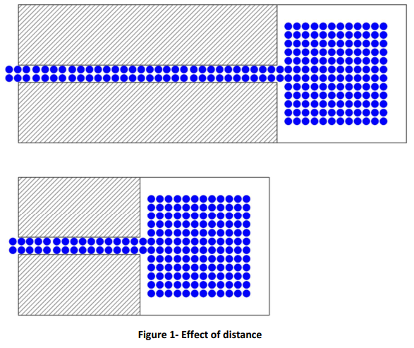
One solution is to relocate the saloon closer to the yard by altering the architectural layout. As shown in Figure 1, shorter corridors mean people walk less and lose less energy—both from reduced exertion and from minimized contact with the walls.
Hydraulic Interpretation
In fire sprinkler systems, shorter pipe lengths reduce friction loss. Less friction loss means more pressure remains available at sprinklers, hose valves, or nozzles.
Case 2: Reducing Traffic
How Lower Flow Rates Reduce Pressure Loss
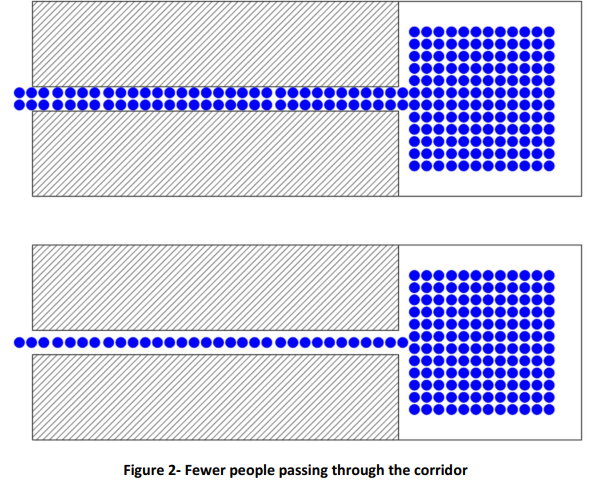
Another solution is to reduce the number of people passing through the corridor at any given time. For example, instead of two people entering the corridor every second, only one person enters. Fewer people in the corridor reduce energy loss because there is less crowding, which means fewer collisions and less contact with the walls.
Hydraulic Interpretation
In sprinkler hydraulics, lower flow rates produce lower friction losses. Since friction loss increases significantly with increased flow, systems with lower hydraulic demand generally require less pressure to operate.
Case 3: Widening the Corridor
How Larger Pipe Diameters Improve Hydraulic Performance
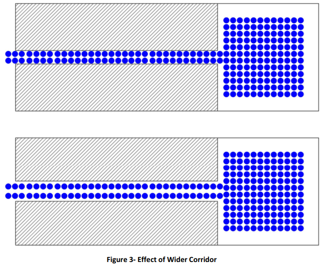
Another approach is to widen the corridor. With a wider corridor, people have more space, reducing their chances of bumping into one another or brushing against the walls. This leads to less energy loss.
Hydraulic Interpretation
Increasing pipe diameter reduces water velocity and decreases friction loss. This is one of the most powerful tools available to fire protection engineers during hydraulic calculations.
Key Insight
Increasing pipe size does not increase sprinkler demand. It reduces friction loss, allowing more pressure to remain available at the remote area.
Case 4: Adding Alternate Routes
Benefits of Looped and Gridded Fire Sprinkler Systems
Adding more corridors allows people to take alternate, less crowded paths to the yard. With less congestion, they encounter fewer obstacles, which minimizes energy loss.
Hydraulic Interpretation
Looped and gridded sprinkler systems provide multiple flow paths, reducing hydraulic resistance and pressure loss compared to traditional tree systems.
Case 5: Boosting Initial Energy
Increasing Available System Pressure
Offering fresh fruit or energy drinks in the saloon gives people more starting energy. With this boost, they can retain enough energy to lift weights once they reach the yard. In Figure 5, people with higher initial energy are represented by red circles.
Hydraulic Interpretation
Higher initial pressure from a fire pump, elevated water tank, or strong municipal water supply helps overcome friction losses and maintain required discharge pressures.
Case 6: Smoothing the Walls
Understanding Pipe Roughness and C-Factor
Smoother walls in the corridor reduce energy loss when people brush against them. The lower image in Figure 6 illustrates how rough walls increase energy loss compared to smoother ones.
Hydraulic Interpretation
Pipe roughness directly affects friction loss. The Hazen-Williams C-Factor is used to represent pipe smoothness in hydraulic calculations.
Linking the Analogy to Hydraulic Systems
Now, let’s translate the analogy into hydraulic and water-based fire protection design concepts. Each element in the example corresponds to a key aspect of hydraulic systems.
Analogy-to-Hydraulics Comparison Table
In a water-based fire protection system, water stored in the tank moves through a network of pipes with sufficient flow rate and pressure. As water travels through the pipes, it experiences friction between water molecules and between water and the pipe walls. This friction results in pressure loss.
For effective fire suppression, water must reach its destination with adequate flow rate and pressure. Without these, controlling, suppressing, or extinguishing a fire may be ineffective.
Applying Hydraulic Principles to Fire Sprinkler System Design
Case 1: Optimal Water Tank Placement
When designing a large site, placing the water tank and fire pumps at the center minimizes pipe length. Shorter pipe distances reduce friction losses and maintain pressure throughout the system.
Case 2: Systems with Lower Water Demand
Light hazard sprinkler systems generally experience lower friction losses than systems designed for higher-risk occupancies such as Extra Hazard Group 2.
Case 3: Larger Pipe Diameters
Larger pipe diameters reduce pressure losses by minimizing friction between water and pipe walls.
Case 4: Looped and Gridded Networks
Looped or gridded piping networks reduce overall pressure losses compared to tree systems because water can flow through multiple routes.
Case 5: Increasing Initial Pressure
Fire pumps or elevated water tanks increase pressure at sprinkler outlets and nozzles.
Case 6: Using Smoother Pipes
Pipes with higher Hazen-Williams C-Factors, such as CPVC and copper, generally experience lower friction losses.
Fire Sprinkler Hydraulic Design Comparison Table
Key Takeaways for NFPA 13 Hydraulic Calculations
Key Insight
Hydraulic calculations are fundamentally an exercise in managing pressure loss. Every design decision—including pipe sizing, network layout, water supply location, pipe material selection, and system demand—affects the balance between available pressure and required pressure.
The Most Important Concepts
- Flow rate influences friction loss.
- Pipe diameter significantly affects pressure loss.
- Pipe roughness affects hydraulic performance.
- Longer pipe runs create greater friction loss.
- Looped networks outperform tree systems hydraulically.
- Fire pumps increase available pressure.
- Proper hydraulic design ensures compliance with NFPA 13 and reliable fire suppression performance.


No comments yet. Be the first to share your thoughts!